
Virtual Class helps you to understand the VMware NSX concepts in simple way. This is my first attempt and hope it will be helpful for NSX Aspirants. The logical switching capability in the NSX platform provides the ability to spin up isolated logical L2 networks with the same flexibility and agility that exists virtual machines. Endpoints, both virtual and physical, can connect to logical segments and establish connectivity independently from their physical location in the data center network. This enabled through the decoupling of network infrastructure from logical network (i.e., underlay network from overlay network) provided by NSX network virtualization.
Multicast Mode: When Multicast replication mode is chosen for a given Logical Switch, NSX relies on the native L2/L3 multicast capability of the physical network to ensure VXLAN encapsulated multi-destination traffic is sent to all VTEPs.
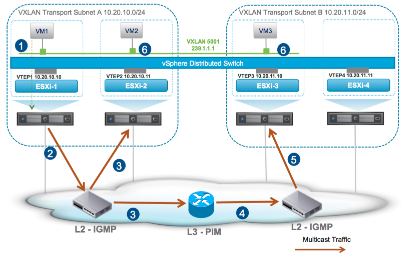
1. VM1 generates a BUM frame.
2. ESXi-1 VXLAN-encapsulates the original frame. The destination IP address in the outer IP header is set to 239.1.1.1 and the multicast packet is sent into the physical network. In this case, ESXi-1 acts as a source for the multicast stream 239.1.1.1.
3. The L2 switch receiving the multicast frame performs replication. Where IGMP snooping is configured on the switch, it will be able to replicate the frame to the relevant interfaces connecting to ESXi-2 and the L3 router. If IGMP snooping is not enabled or supported, the L2 switch treats the frame as an L2 broadcast packet and replicates it to all interfaces belonging to the same VLAN of the port where the packet was received.
4. The L3 router performs L3 multicast replication and sends the packet into the transport subnet B
5. The L2 switch behaves similarly to what discussed at step 3 and replicates the frame.
6. ESXi-2 and ESXI-3 de-capsulate the received VXLAN packets, exposing the original Ethernet frames that are then delivered to VM2 and VM3.
Unicast Mode: Unicast mode represents the opposite approach from multicast mode, wherein the decoupling of logical and physical networks is fully achieved. In unicast mode, the ESXi hosts in the NSX domain are divided in separate groups (i.e., VTEP segments) based on the IP subnet of VTEP interfaces
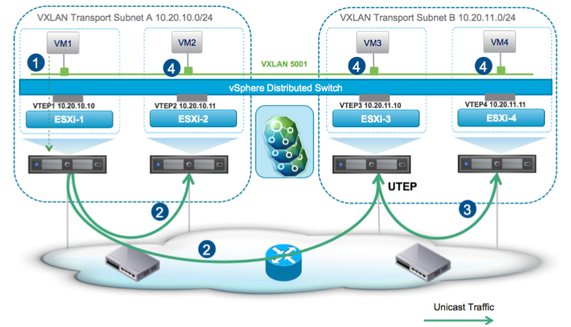
1. VM1 generates a BUM frame to be sent to each VM connected to Logical Switch 5001. In this instance there is no need to specify a multicast group associated to this VXLAN segment.
2. ESXi1 references its local VTEP table. This table is filled with the information received via control plane communication with the controller nodes. The check validates the need to replicate the packet to the other VTEP belonging to the local segment, ESXi2, as well as to the UTEP part of remote segments, ESXi3. The unicast copy sent to the UTEP has a specific bit set in the VXLAN header – the “REPLICATE_LOCALLY” bit – as an indication to the UTEP that this frame is coming from a remote VTEP segment and may need to be locally replicated.
3. The UTEP receives the frame, references the local VTEP table, and replicates it to all the ESXi hosts which are part of the local VTEP segment with at least one VM connected to VXLAN 5001. In this example, that is simply ESXi-4.
Hybrid Mode: Hybrid mode offers operational simplicity similar to unicast mode – IP multicast routing configuration is not required in the physical network – while leveraging the L2 multicast capability of physical switches.
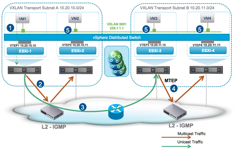
1. VM1 generates a BUM frame which must be replicated to all VMs that are part of VXLAN 5001. The multicast group 239.1.1.1 must be associated with the VXLAN segment, as multicast encapsulation is performed for local traffic replication.
2. ESXi1 encapsulates the frame in a multicast packet addressed to the 239.1.1.1 group. Layer 2 multicast configuration in the physical network is leveraged to ensure that the VXLAN frame is delivered to all VTEPs in the local VTEP segment. In hybrid mode the ESXi hosts send an IGMP join when there are local VMs interested in receiving multi-destination traffic, similar to Figure 28). Since PIM is not required, it is strongly recommended to define an IGMP querier per VLAN to ensure successful L2 multicast delivery and avoid non-deterministic behavior. When IGMP snooping is enabled, but there’s no IGMP querier definition, some Ethernet switches will resort to flooding the multicast traffic in the VLAN while others will drop it. Please refer to the documentation provided by your vendor of choice.
3. At the same time ESXi-1 looks at the local VTEP table and determines the need to replicate the packet to the MTEP part of remote segments, in this case ESXi3. The unicast copy is sent to the MTEP with the corresponding bit set in the VXLAN header as an indication to the MTEP that this frame is coming from a remote VTEP segment and needs to be locally reinjected in the network.
4. The MTEP creates a multicast packet and sends it to the physical network where will be replicated by the local L2 switching infrastructure.
This step by step process helps you to understand different modes and traffic replication modes in NSX. Thanks again and looking forward to write more Virtual Classes related to NSX.